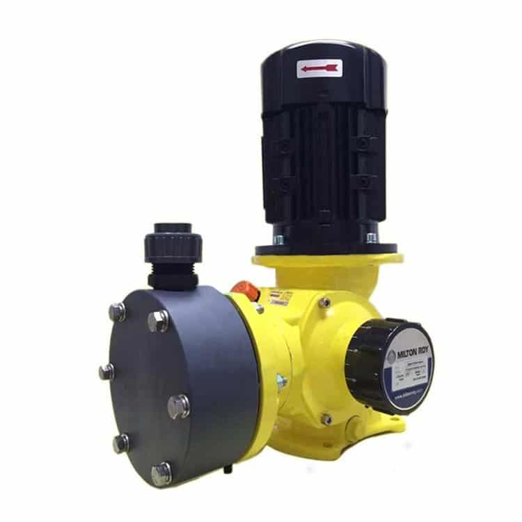
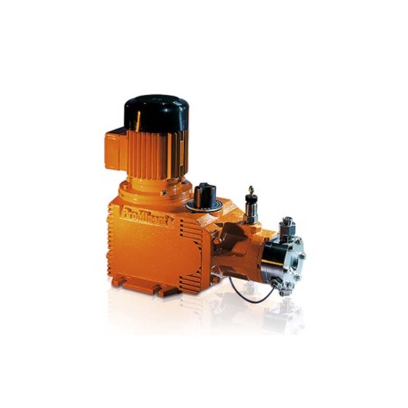
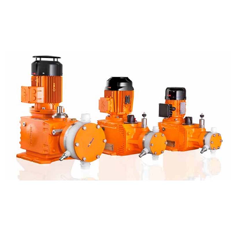
The HYDRO API 675 is a safe and durable hydraulic diaphragm dosing pump that meets API 675 safety standards. It features a PTFE multi-layer diaphragm with monitoring, full-motion drive, and automatic bleeding, ensuring exceptional safety. Its modular construction also makes it versatile for various industries.
The API 675 hydraulic diaphragm pump form an integrated product range with stroke lengths of 15 or 20 mm. Equipped with full-motion drive and automatic bleeding, they therefore cover the capacity range of 7 to 1506 l/h at 100 – 7 bar. They also meet the requirements of API 675.
Excellent process reliability:
Excellent flexibility:
| Plunger Ø | Max. pressure | Max. pump capacity in l/h at strokes/min | Theor. stroke volume | Suction lift | |||||
|---|---|---|---|---|---|---|---|---|---|
| 50 | 60 | 125 | 150 | 187 | 214 | ||||
| mm | bar | l/h | l/h | l/h | l/h | l/h | l/h | ml/stroke | m WC |
9 |
100 |
[0.4] |
[0.8] |
[1.5] |
[1.9] |
[2.5] |
[3.0] |
0.9 |
3.0 |
9 |
64 |
[1.0] |
(1.3)-1.3 |
(2.9)-2.9 |
(3.1)-3.1 |
(4.0)-4.8 |
(4.8)-5.3 |
0.9 |
3.0 |
9 |
40 |
(1.4)-1.4 |
(1.7)-1.8 |
(2.7)–3.9 |
(3.6)–4.7 |
(4.0)–6.0 |
(5.5)–6.8 |
0.9 |
3.0 |
9 |
25 |
(1.7)-1.8 |
(1.7)-2.1 |
(2.8)–4.5 |
(3.8)–5.6 |
(4.6)–7.0 |
(5.5)–8.0 |
0.9 |
3.0 |
9 |
10 |
(1.7)-2.1 |
(1.7)-2.5 |
(2.8)–5.2 |
(3.8)–6.3 |
(4.6)–7.8 |
(5.5)–9.1 |
0.9 |
3.0 |
12 |
100 |
(2.4)-2.4 |
(2.9)-2.9 |
(5.5)–6.0 |
(7.4)–7.4 |
(8.0)–9.3 |
(9.0)-10.1 |
1.7 |
3.0 |
12 |
64 |
(2.0)-3.0 |
(2.8)-3.6 |
(4.5)–7.7 |
(7.0)–9.1 |
(8.0)-11.4 |
(9.0)-13.0 |
1.7 |
3.0 |
12 |
40 |
(2.2)-3.4 |
(2.5)-4.1 |
(4.5)–8.7 |
(6.0)-10.4 |
(7.0)-13.0 |
(9.0)-14.7 |
1.7 |
3.0 |
12 |
25 |
(2.2)-3.5 |
(2.3)-4.5 |
(4.8)–9.4 |
(6.0)-11.1 |
(7.0)-13.8 |
(9.0)-15.9 |
1.7 |
3.0 |
12 |
10 |
(2.2)-3.7 |
(2.5)-4.8 |
(4.8)-10.1 |
(6.0)-12.1 |
(7.0)-15.1 |
(9.0)-17.1 |
1.7 |
3.0 |
| Plunger Ø | Max. pressure | Max. pump capacity in l/h at strokes/min | Theor. stroke volume | Suction lift | Connection on suction/discharge side | Shipping weight | ||||
|---|---|---|---|---|---|---|---|---|---|---|
| 60 | 72 | 149 | 180 | 224 | ||||||
| mm | bar | l/h | l/h | l/h | l/h | l/h | ml/stroke | m WC | G-DN | kg |
| 9 | 100 | [0.5] | [0.8] | [1.8] | [2.0] | [3.0] | 0.9 | 3.0 | DN 3 | 31 |
| 9 | 64 | [1.2] | (1.6)-1.6 | (3.3)-3.3 | (3.7)- 3.7 | (4.8)- 5.7 | 0.9 | 3.0 | DN 3 | 31 |
| 9 | 40 | (1.7)-1.7 | (2.0)-2.1 | (3.2)-4.6 | (4.3)- 5.6 | (4.8)- 7.2 | 0.9 | 3.0 | DN 3 | 31 |
| 9 | 25 | (2.0)-2.1 | (2.0)-2.5 | (3.4)-5.4 | (4.5)- 6.7 | (5.5)- 8.4 | 0.9 | 3.0 | DN 3 | 31 |
| 9 | 10 | (2.0)-2.5 | (2.0)-3.0 | (3.4)-6.2 | (4.5)- 7.5 | (5.5)- 9.3 | 0.9 | 3.0 | DN 3 | 31 |
| 12 | 100 | (2.8)-2.8 | (3.5)-3.5 | (6.6)-7.2 | (8.8)- 8.8 | (9.6)-11.1 | 1.7 | 3.0 | DN 3 | 31 |
| 12 | 64 | (2.4)-3.6 | (3.4)-4.3 | (5.4)-9.2 | (8.4)-10.9 | (9.6)-13.6 | 1.7 | 3.0 | DN 3 | 31 |
| 12 | 40 | (2.6)-4.0 | (3.0)-4.9 | (5.4)-10.4 | (7.2)-12.4 | (8.4)-15.6 | 1.7 | 3.0 | DN 3 | 31 |
| 12 | 25 | (2.6)-4.4 | (3.0)-5.4 | (5.7)-11.2 | (7.2)-13.3 | (8.4)-16.5 | 1.7 | 3.0 | DN 3 | 31 |
| 12 | 10 | (2.6)-4.4 | (3.0)-5.7 | (5.7)-12.1 | (7.2)-14.5 | (8.4)-18.1 | 1.7 | 3.0 | DN 3 | 31 |
Piston Ø 9 and 12, version with double ball valves.
The permitted rated flow configuration is possible in the stated range when pumps are selected in accordance with API 675 (control range 1:10).
The litre capacity indicated using […] is the maximum litre capacity with an applicable control range of 1:5 and does not therefore satisfy API 675.
Example: a 12 mm piston, 40 bar pressure and stroke rate of 125 strokes/min results in (4.5) – 8.7, i.e. the control range of 1:10 is met for a rated flow of between 4.5 l/h and 8.7 l/h.
| Identity code of material | Dosing head | Suction/discharge connection | Seals/ball seat | Balls |
|---|---|---|---|---|
| S1 | Stainless steel 1.4571/1.4404 | Stainless steel 1.4581 | PTFE/stainless steel 1.4404 | Ceramic |
| Identity code specification | Power supply | Remarks | |||
| S | 3-phase, IP 55* | 230V/400V | 50Hz | 0.37kW | |
| T | 3-phase, IP 55* | 230V/400V 265V/460V |
50Hz 60Hz |
0.37kW | With PTC, speed control range 1:5 |
| R | 3-phase, IP 55* | 230V/400V | 50Hz | 0.37kW | With PTC, speed control range 1:20, with external fan 1-phase 230 V; 50/60 Hz |
| V | 1-phase, IP 55* | 230V | 50Hz | 0.37kW | Variable speed stroke control motor with integrated frequency converter |
| L | 3-phase, II 2G Ex de IIC T4 Gb | 230V/400V | 50Hz | 0.37kW | With PTC, speed control range 1:5 |
| Q | 3-phase, II 2G Ex de IIC T4 | 265V/460V | 60Hz | 0.37kW | With PTC, speed control range 1:5 |
* Three-phase motor according to IEC 60034-1
Motor data sheets can be requested for more information. Versions 265/460V – 60Hz, special motors or special motor flanges are available on request.
Information for use in areas at risk from explosion
Only use pumps with the appropriate labelling in line with the ATEX Directive 2014/34/EC in premises at risk from explosion. Ensure that the explosion group, category and degree of protection specified on the label correspond to or are superior to the conditions prevalent in the intended application.
| Plunger Ø | Max. pressure | Max. pump capacity in l/h at strokes/min | Theor. stroke volume | Suction lift | Connection on suction/discharge side | Shipping weight | ||||
|---|---|---|---|---|---|---|---|---|---|---|
| 60 | 125 | 150 | 187 | 214 | ||||||
| mm | bar | l/h | l/h | l/h | l/h | l/h | ml/stroke | m WC | G-DN | kg |
| * SST version with double ball valve, valve connector on the suction-discharge side with female thread Rp 1/4 and male thread G 3/4 – DN 10 | ||||||||||
| ** HV design with G1 – DN 15 connector | ||||||||||
| 16 | 100 | [3.0] | [6.5] | (8.5)-8.5 | (10)-11 | (12)-13 | 3.0 | 3.0 | Rp 1/4 – DKV * | 31 |
| 16 | 64 | [4.0] | (10)-10 | (10)-13 | (12)-16.5 | (14)-18.5 | 3.0 | 3.0 | Rp 1/4 – DKV * | 31 |
| 16 | 40 | [5.5] | (10)-13 | (12)-15.5 | (14)-19.5 | (16)-23.5 | 3.0 | 3.0 | Rp 1/4 – DKV * | 31 |
| 16 | 25 | [6.5] | (12)-14.5 | (14)-17.5 | (17)-22.5 | (20)-26.5 | 3.0 | 3.0 | Rp 1/4 – DKV * | 31 |
| 16 | 10 | (7)-7.5 | (13)-16.5 | (15)-19.5 | (18)-24.5 | (22)-29.5 | 3.0 | 3.0 | Rp 1/4 – DKV * | 31 |
| 18 | 64 | [6.5] | (12)-15.5 | (18.5)-18.5 | (24.5)-24.5 | (26)-26.5 | 3.8 | 3.0 | G 3/4 – 10 ** | 31 |
| 18 | 40 | (7)-8 | (13)-18.5 | (22)-22 | (26)-28.5 | (26)-32.5 | 3.8 | 3.0 | G 3/4 – 10 ** | 31 |
| 18 | 25 | (8)-9 | (16)-19.5 | (23)-24.5 | (26)-30.5 | (28)-35.5 | 3.8 | 3.0 | G 3/4 – 10 ** | 31 |
| 18 | 10 | (8)-10 | (16)-21.5 | (23)-26.5 | (29)-33.5 | (28)-37.5 | 3.8 | 3.0 | G 3/4 – 10 ** | 31 |
| 22 | 40 | (7)-7.5 | (20)-25.5 | (27)-28.5 | (37)-42.5 | (44)-48 | 5.7 | 3.0 | G 3/4 – 10 ** | 31 |
| 22 | 25 | (7)-8.5 | (20)-25.5 | (25)-33.5 | (35)-43.5 | (40)-51 | 5.7 | 3.0 | G 3/4 – 10 ** | 31 |
| 22 | 10 | (8)-10 | (17)-28.5 | (25)-36.5 | (30)-47 | (40)-54 | 5.7 | 3.0 | G 3/4 – 10 ** | 31 |
| 26 | 25 | (20)-22 | (35)-49 | (40)-59 | (65)-72 | (50)-83 | 7.9 | 3.0 | G 3/4 – 10 ** | 31 |
| 26 | 10 | (20)-23.5 | (30)-51 | (35)-61 | (40)-76 | (45)-86 | 7.9 | 3.0 | G 3/4 – 10 ** | 31 |
| Plunger Ø | Max. pressure | Max. pump capacity in l/h at strokes/min | Theor. stroke volume | Suction lift | Connection on suction/discharge side | Shipping weight | |||
|---|---|---|---|---|---|---|---|---|---|
| 72 | 149 | 180 | 224 | ||||||
| mm | bar | l/h | l/h | l/h | l/h | ml/stroke | m WC | G-DN | kg |
| * SST version with double ball valve, valve connector on the suction-discharge side with female thread Rp 1/4 and male thread G 3/4 – DN 10 | |||||||||
| ** HV design with G1 – DN 15 connector | |||||||||
| 16 | 100 | [3.5] | [7.5] | (10)-10 | (12)-13 | 3.0 | 3.0 | Rp 1/4 – DKV * | 31 |
| 16 | 64 | [4.5] | (10)-11.5 | (12)-15.5 | (14.5)-19.5 | 3.0 | 3.0 | Rp 1/4 – DKV * | 31 |
| 16 | 40 | [6.5] | (12)-15.5 | (14.5)-18.5 | (16.5)-23 | 3.0 | 3.0 | Rp 1/4 – DKV * | 31 |
| 16 | 25 | [7.5] | (14.5)-17 | (16.5)-21 | (20.5)-27 | 3.0 | 3.0 | Rp 1/4 – DKV * | 31 |
| 16 | 10 | (8.5)-9 | (15.5)-19.5 | (18)-23 | (21.5)-29 | 3.0 | 3.0 | Rp 1/4 – DKV * | 31 |
| 18 | 64 | [7.5] | (14.5)-18.5 | (22)-22 | (29)-29 | 3.8 | 3.0 | G 3/4 – 10 ** | 31 |
| 18 | 40 | (8.5)-9.5 | (15.5)-22 | (26)-26 | (31)-34 | 3.8 | 3.0 | G 3/4 – 10 ** | 31 |
| 18 | 25 | (9.5)-10.5 | (19.5)-23 | (27.5)-29 | (31)-36.5 | 3.8 | 3.0 | G 3/4 – 10 ** | 31 |
| 18 | 10 | (9.5)-12 | (19.5)-25.5 | (27.5)-31.5 | (34.5)-40 | 3.8 | 3.0 | G 3/4 – 10 ** | 31 |
| 22 | 40 | (8.5)-9 | (24)-30 | (32.5)-34 | (44)-50.5 | 5.7 | 3.0 | G 3/4 – 10 ** | 31 |
| 22 | 25 | (8.5)-10 | (24)-30 | (30)-40 | (42)-52 | 5.7 | 3.0 | G 3/4 – 10 ** | 31 |
| 22 | 10 | (9.5)-12 | (20)-34 | (36) -56 | (44)-50.5 | 5.7 | 3.0 | G 3/4 – 10 ** | 31 |
| 26 | 25 | (24)-26 | (42)-58 | (48)-70.5 | (78)-86 | 7.9 | 3.0 | G 3/4 – 10 ** | 31 |
| 26 | 10 | (24)-28 | (36)-60.5 | (42)-73 | (48)-91 | 7.9 | 3.0 | G 3/4 – 10 ** | 31 |
The permitted rated flow configuration is possible in the stated range when pumps are selected in accordance with API 675 (control range 1:10).
The litre capacity indicated using […] is the maximum litre capacity with an applicable control range of 1:5 and does not therefore satisfy API 675.
Example: with 16 mm piston, pressure 25 bar and stroke rate of 150 strokes/min gives (14) – 17.5, i.e. the control range of 1:10 is met for a rated flow of between 14 l/h and 17.5 l/h.
PVDF version max. 25 bar, PTFE + 25 % carbon; PTFE up to 16 bar
| Identity code of material | Dosing head | Connection on suction/discharge side | Seals/ball seat | Balls |
|---|---|---|---|---|
| P1 | PVDF | PVDF | PTFE/PTFE + 25 % carbon | Ceramic |
| S1 | Stainless steel 1.4571/1.4404 | Stainless steel 1.4581 | PTFE/stainless steel 1.4404 | Ceramic |
| T1 | PTFE + 25% carbon | PVDF | PTFE/PTFE + 25 % carbon | Ceramic |
| Identity code specification | Power supply | Remarks | |||
| S | 3-phase, IP 55* | 230V/400V | 50Hz | 0.37kW | |
| T | 3-phase, IP 55* | 230V/400V 265V/460V |
50Hz 60Hz |
0.37kW | With PTC, speed control range 1:5 |
| R | 3-phase, IP 55* | 230V/400V | 50Hz | 0.45kW | With PTC, speed control range 1:20, with external fan 1-phase 230 V; 50/60 Hz |
| V | 1-phase, IP 55* | 230V | 50Hz | 0.37kW | Variable speed stroke control motor with integrated frequency converter |
| L | 3-phase, II 2G Ex de IIC T4 Gb | 230V/400V | 50Hz | 0.37kW | With PTC, speed control range 1:5 |
| Q | 3-phase, II 2G Ex de IIC T4 | 265V/460V | 60Hz | 0.37kW | With PTC, speed control range 1:5 |
* 3-phase AC motor in accordance with IEC 60034-1
Motor data sheets can be requested for more information. 265/460V – 60Hz versions, special motors or special motor flanges are available on request.
Information for use in areas at risk from explosion
Only use pumps with the appropriate labelling in line with the ATEX Directive 2014/34/EC in premises at risk from explosion. Ensure that the explosion group, category and degree of protection specified on the label correspond to or are superior to the conditions prevalent in the intended application.
| Plunger Ø | Max. pressure | Max. pump capacity in l/h at strokes/min | Theor. stroke volume | Suction lift | Connection on suction/discharge side | Shipping weight | ||||
|---|---|---|---|---|---|---|---|---|---|---|
| 60 | 125 | 150 | 187 | 214 | ||||||
| mm | bar | l/h | l/h | l/h | l/h | l/h | ml/stroke | m WC | G-DN | kg |
| * SST version with double ball valve, valve connector on the suction-discharge side with female thread Rp 1/4 and male thread G 3/4 – DN 10 | ||||||||||
| ** HV design with G1 – DN 15 connector | ||||||||||
| *** HV design (SST only) with 1 1/4″ – DN 20 connector | ||||||||||
| 22 | 100 | [9.0] | [19.0] | [25.0] | [30.5] | [32.0] | 5.7 | 3.0 | Rp 3/8 – 10-DKV * | 41 |
| 22 | 64 | [11.0] | [26.0] | [31.5] | [40.0] | [46.0] | 5.7 | 3.0 | Rp 3/8 – 10-DKV * | 41 |
| 22 | 40 | [12.0] | [28.5] | [35.5] | [45.0] | [51.5] | 5.7 | 3.0 | Rp 3/8 – 10-DKV * | 41 |
| 22 | 25 | [12.5] | [30.5] | [37.0] | [47.0] | [55.0] | 5.7 | 3.0 | Rp 3/8 – 10-DKV * | 41 |
| 22 | 10 | [13.5] | [31.5] | [39.0] | [50.0] | [57.5] | 5.7 | 3.0 | Rp 3/8 – 10-DKV * | 41 |
| 26 | 64 | (18)-19 | (35)-43.5 | (40)-51.5 | (55)-63 | (65)-73 | 7.9 | 3.0 | G 3/4 – 10 ** | 41 |
| 26 | 40 | (18)-21 | (37)-45.5 | (40)-55 | (50)-71 | (70)-81 | 7.9 | 3.0 | G 3/4 – 10 ** | 41 |
| 26 | 25 | (15)-21 | (30)-49.5 | (40)-59 | (55)-74 | (70)-84 | 7.9 | 3.0 | G 3/4 – 10 ** | 41 |
| 26 | 10 | (15)-22 | (30)-49.5 | (35)-61 | (50)-77 | (80)-87 | 7.9 | 3.0 | G 3/4 – 10 ** | 41 |
| 32 | 40 | (25)-25.5 | (50)-66 | (70)-80 | (65)-101.5 | (70)-116.5 | 12.0 | 3.0 | G 1 – 15 *** | 41 |
| 32 | 25 | (25)-26.5 | (50)-69 | (65)-83 | (65)-105.5 | (70)-122.5 | 12.0 | 3.0 | G 1 – 15 *** | 41 |
| 32 | 10 | (22)-31.5 | (50)-74 | (70)-90 | (60)-112.5 | (65)-129 | 12.0 | 3.0 | G 1 – 15 *** | 41 |
| 38 | 25 | (25)-50.5 | (70)-110.5 | (80)-126 | (150)-166 | (180)-187 | 17.0 | 3.0 | G 1 – 15 *** | 41 |
| 38 | 10 | (30)-51.5 | (80)-111.5 | (90)-135 | (150)-168 | (180)-191 | 17.0 | 3.0 | G 1 – 15 *** | 41 |
| Plunger Ø | Max. pressure | Max. pump capacity in l/h at strokes/min | Theor. stroke volume | Suction lift | Connection on suction/discharge side | Shipping weight | |||
|---|---|---|---|---|---|---|---|---|---|
| 72 | 149 | 180 | 224 | ||||||
| mm | bar | l/h | l/h | l/h | l/h | ml/stroke | m WC | G-DN | kg |
| * SST version with double ball valve, valve connector on the suction-discharge side with female thread Rp 1/4 and male thread G 3/4 – DN 10 | |||||||||
| ** HV design with G1 – DN 15 connector | |||||||||
| *** HV design (SST only) with 1 1/4″ – DN 20 connector | |||||||||
| 22 | 100 | [10.0] | [22.0] | [29.5] | [36.5] | 5.7 | 3.0 | Rp 3/8 – 10-DKV * | 41 |
| 22 | 64 | [13.0] | [30.5] | [38.0] | [47.5] | 5.7 | 3.0 | Rp 3/8 – 10-DKV * | 41 |
| 22 | 40 | [14.5] | [34.0] | [42.5] | [53.5] | 5.7 | 3.0 | Rp 3/8 – 10-DKV * | 41 |
| 22 | 25 | [15.0] | [36.5] | [44.5] | [56.0] | 5.7 | 3.0 | Rp 3/8 – 10-DKV * | 41 |
| 22 | 10 | [16.0] | [37.5] | [47.0] | [59.5] | 5.7 | 3.0 | Rp 3/8 – 10-DKV * | 41 |
| 26 | 64 | (21.5)-22.5 | (42)-51.5 | (48)-61.5 | (66)-75 | 7.9 | 3.0 | G 3/4 – 10 ** | 41 |
| 26 | 40 | (21.5)-25 | (44)-54 | (48)-66 | (60)-85 | 7.9 | 3.0 | G 3/4 – 10 ** | 41 |
| 26 | 25 | (18)-25 | (36)-59 | (48)-70.5 | (66)-88.5 | 7.9 | 3.0 | G 3/4 – 10 ** | 41 |
| 26 | 10 | (18)-26 | (36)-59 | (42)-73 | (60)-92 | 7.9 | 3.0 | G 3/4 – 10 ** | 41 |
| 32 | 40 | (30)-30.5 | (60)-78.5 | (84)-96 | (78)-121 | 12.0 | 3.0 | G 1 – 15 *** | 41 |
| 32 | 25 | (30)-31.5 | (60)-82 | (78)-99.5 | (78)-126 | 12.0 | 3.0 | G 1 – 15 *** | 41 |
| 32 | 10 | (26.5)-37.5 | (60)-88 | (84)-108 | (72)-134.5 | 12.0 | 3.0 | G 1 – 15 *** | 41 |
| 38 | 25 | (30)-60.5 | (84)-131 | (96)-151 | (180)-198 | 17.0 | 3.0 | G 1 – 15 *** | 41 |
| 38 | 10 | (36)-61.5 | (96)-132 | (108)-162 | (180)-201 | 17.0 | 3.0 | G 1 – 15 *** | 41 |
The permitted rated flow configuration is possible in the stated range when pumps are selected in accordance with API 675 (control range 1:10).
The litre capacity indicated using […] is the maximum litre capacity with an applicable control range of 1:5 and does not therefore satisfy API 675.
Example: a 26 mm piston, 25 bar pressure and stroke rate of 150 strokes/min results in (40) – 59, i.e. the control range of 1:10 is met for a rated flow of between 40 l/h and 59 l/h.
PVDF version max. 25 bar, PTFE + 25 % carbon; PTFE up to 16 bar
| Identity code of material | Dosing head | Connection on suction/discharge side | Seals/ball seat | Balls |
|---|---|---|---|---|
| P1 | PVDF | PVDF | PTFE/PTFE + 25 % carbon | Ceramic |
| S1 | Stainless steel 1.4571/1.4404 | Stainless steel 1.4581 | PTFE/ZrO2 (DN 15/DN20 stainless steel 1.4404) | Ceramic |
| T1 | PTFE + 25% carbon | PVDF | PTFE/PTFE + 25 % carbon | Ceramic |
| Identity code specification | Power supply | Remarks | |||
| S | 3-phase, IP 55* | 230V/400V | 50Hz | 0.75kW | |
| T | 3-phase, IP 55* | 230V/400V 265V/460V |
50Hz 60Hz |
0.75kW | With PTC, speed control range 1:5 |
| R | 3-phase, IP 55* | 230V/400V | 50Hz | 0.75kW | With PTC, speed control range 1:20, with external fan 1-phase 230 V; 50/60 Hz |
| V | 1-phase, IP 55* | 230V | 50Hz | 0.75kW | Variable speed stroke control motor with integrated frequency converter |
| L | 3-phase, II 2G Ex de IIC T4 | 230V/400V | 50Hz | 0.75kW | With PTC, speed control range 1:5 |
| Q | 3-phase, II 2G Ex de IIC T4 | 265V/460V | 60Hz | 0.75kW | With PTC, speed control range 1:5 |
* 3-phase AC motor in accordance with IEC 60034-1
Motor data sheets can be requested for more information. 265/460V – 60Hz versions, special motors or special motor flanges are available on request.
Information for use in areas at risk from explosion
Only use pumps with the appropriate labelling in line with the ATEX Directive 2014/34/EC in premises at risk from explosion. Ensure that the explosion group, category and degree of protection specified on the label correspond to or are superior to the conditions prevalent in the intended application.
| Plunger Ø | Max. pressure | Max. pump capacity in l/h at strokes/min | Theor. stroke volume | Suction lift | Connection on suction/discharge side | ||||
|---|---|---|---|---|---|---|---|---|---|
| 71 | 103 | 136 | 188 | 214 | |||||
| mm | bar | l/h | l/h | l/h | l/h | l/h | ml/stroke | m WC | G-DN |
| 40 | 40 | [79] | [118] | (150)-154 | (200)-211 | (220)-242 | 25.1 | 3 | G 1 1/2 A – DN 25 |
| 40 | 25 | [80] | [121] | (150)160 | (200)-219 | (220)-250 | 25.1 | 3 | G 1 1/2 A – DN 25 |
| 40 | 16 | [82] | [125] | [162] | (200)-225 | (220)-254 | 25.1 | 3 | G 1 1/2 A – DN 25 |
| 40 | 10 | [83] | (100)-125 | (150)-166 | (200)-228 | (220)-256 | 25.1 | 3 | G 1 1/2 A – DN 25 |
| 40 | 7 | [84] | (100)-127 | (150)-167 | (200)-230 | (220)-261 | 25.1 | 3 | G 1 1/2 A – DN 25 |
| 52 | 25 | [142] | (200)-204 | (200)-271 | (370)-372 | [425] | 42.4 | 3 | G 1 1/2 A – DN 25 |
| 52 | 16 | [143] | (190)-205 | (200)-274 | (370)-376 | [425] | 42.4 | 3 | G 1 1/2 A – DN 25 |
| 52 | 10 | [144] | (180)-207 | (200)-276 | (370)-379 | [426] | 42.4 | 3 | G 1 1/2 A – DN 25 |
| 52 | 7 | [145] | (180)-209 | (200)-277 | [380] | [426] | 42.4 | 3 | G 1 1/2 A – DN 25 |
| 63 | 16 | (200)-212 | (280)-306 | (390)-401 | [562] | [635] | 62.3 | 3 | G 1 1/2 A – DN 25 |
| 63 | 10 | (210)-215 | (280)-311 | (380)-407 | [562] | [638] | 62.3 | 3 | G 1 1/2 A – DN 25 |
| 63 | 7 | (210)-216 | (280)-312 | (370)-408 | [564] | [648] | 62.3 | 3 | G 1 1/2 A – DN 25 |
| 80 | 10 | (280)-350 | (420)-509 | (580)-657 | (890)-914 | (1,050)-1,056 | 100.4 | 3 | G 2 A – DN 32 |
| 80 | 7 | (270)-352 | (420)-513 | (590)-683 | (890)-947 | (1,050)-1,080 | 100.4 | 3 | G 2 A – DN 32 |
| 94 | 7 | (350)-493 | (500)-710 | (820)-936 | (1,000)-1,258 | (1,400)-1,440 | 138.7 | 3 | G 2 1/2 A – DN 40 |
| Plunger Ø | Max. pressure | Max. pump capacity in l/h at strokes/min | Theor. stroke volume | Suction lift | Connection on suction/discharge side | Shipping weight | |||
|---|---|---|---|---|---|---|---|---|---|
| 86 | 124 | 164 | 225 | ||||||
| mm | bar | l/h | l/h | l/h | l/h | ml/stroke | m WC | G-DN | kg |
| 40 | 40 | [95] | [142] | (180)-200 | (240)-252 | 25.1 | 3 | G 1 1/2 A – DN 25 | 69 |
| 40 | 25 | [96] | [145] | (180)-185 | (240)-262 | 25.1 | 3 | G 1 1/2 A – DN 25 | 69 |
| 40 | 16 | [99] | [150] | [195] | (240)-269 | 25.1 | 3 | G 1 1/2 A – DN 25 | 69 |
| 40 | 10 | [100] | (120)-150 | (180)-200 | (240)-272 | 25.1 | 3 | G 1 1/2 A – DN 25 | 69 |
| 40 | 7 | [101] | (120)-152 | (180)-201 | (240)-275 | 25.1 | 3 | G 1 1/2 A – DN 25 | 69 |
| 52 | 25 | [171] | (240)-245 | (240)-327 | (440)-445 | 42.4 | 3 | G 1 1/2 A – DN 25 | 69 |
| 52 | 16 | [172] | (230)-246 | (240)-330 | (450)-450 | 42.4 | 3 | G 1 1/2 A – DN 25 | 69 |
| 52 | 10 | [174] | (220)-249 | (240)-333 | (450)-455 | 42.4 | 3 | G 1 1/2 A – DN 25 | 69 |
| 52 | 7 | [176] | (220)-251 | (240)-334 | [454] | 42.4 | 3 | G 1 1/2 A – DN 25 | 69 |
| 63 | 16 | (245)-256 | (340)-368 | (470)-483 | [672] | 62.3 | 3 | G 1 1/2 A – DN 25 | 76 |
| 63 | 10 | (255)-260 | (340)-374 | (460)-490 | [672] | 62.3 | 3 | G 1 1/2 A – DN 25 | 76 |
| 63 | 7 | (260)-262 | (340)-375 | (445)-491 | [674] | 62.3 | 3 | G 1 1/2 A – DN 25 | 76 |
| 80 | 10 | (340)-424 | (505)-613 | (700)-792 | (1,065)-1,094 | 100.4 | 3 | G 2 A – DN 32 | 87 |
| 80 | 7 | (330)-426 | (505)-618 | (711)-823 | (1,065)-1,133 | 100.4 | 3 | G 2 A – DN 32 | 87 |
| 94 | 7 | (430)-597 | (600)-854 | (990)-1,128 | (1,200)-1,506 | 138.7 | 3 | G 2 1/2 A – DN 40 | 96 |
The permitted rated flow configuration is possible in the stated range when pumps are selected in accordance with API 675 (control range 1:10).
The litre capacity indicated using […] is the maximum litre capacity with an applicable control range of 1:5 and does not therefore satisfy API 675.
Example: with 52 mm piston, 10 bar pressure and stroke rate of 136 strokes/min results in (200) – 276, i.e. the control range of 1:10 is met for a rated flow of between 200 l/h and 276 l/h.
PVDF version max. 25 bar, PTFE + 25 % carbon; PTFE up to 10 bar
| Identity code of material | Dosing head | Connection on suction/discharge side | Seals | Valve seats | Valve balls up to DN 25 | Valve plates/valve springs |
|---|---|---|---|---|---|---|
| P1 | PVDF | PVDF | PTFE | PTFE + 25% carbon | Glass | Ceramic/E-CTFE |
| S1 | Stainless steel 1.4404 | Stainless steel 1.4404 | PTFE | PTFE | Stainless steel 1.4401 | Stainless steel 1.4404/Hastelloy C |
| T1 | PTFE + 25% carbon | PVDF | PTFE | PTFE + 25% carbon | Glass | Ceramic/E-CTFE |
| V1 | PVC | PVDF | PTFE | PTFE | Glass | Ceramic/E-CTFE |
| Y1 | PPT | PVDF | PTFE | PTFE | Glass | Ceramic/E-CTFE |
| Identity code specification | Power supply | Remarks | |||
| S | 3-phase, IP 55* | 230V/400V | 50Hz | 1.1kW | |
| T | 3-phase, IP 55* | 230V/400V 265V/460V |
50Hz 60Hz |
1.1kW | With PTC, speed control range 1:5 |
| R | 3-phase, IP 55* | 230V/400V | 50Hz | 1.5kW | With PTC, speed control range 1:20, with external fan 1-phase 230 V; 50/60 Hz |
| V | 3-phase, IP 55* | 400V | 50Hz | 1.5kW | Variable speed stroke control motor with integrated frequency converter |
| L | 3-phase, II 2G Ex de IIC T4 Gb | 230V/400V | 50Hz | 1.1kW | With PTC, speed control range 1:5 |
| Q | 3-phase, II 2G Ex de IIC T4 | 265V/460V | 60Hz | 1.1kW | With PTC, speed control range 1:5 |
* 3-phase AC motor in accordance with IEC 60034-1
Motor data sheets can be requested for more information. 265/460V – 60Hz versions, special motors or special motor flanges are available on request.
Information for use in areas at risk from explosion
Only use pumps with the appropriate labelling in line with the ATEX Directive 2014/34/EC in premises at risk from explosion. Ensure that the explosion group, category and degree of protection specified on the label correspond to or are superior to the conditions prevalent in the intended application.
The following list of applications are general examples of generally suitable applications for this product. Please contact your local sales representative to talk about the applicable use of this product in your specific case / environment.
‘HAOSH‘ is a major dosing metering pump brand of Shanghai GL Environmental Technology Co., Ltd. Also as a pump category super market, we supply diaphragm pumps, chemical pumps, water pumps, screw pumps, etc. Since founded in 2007, HAOSH brand has for more than 100 countries of the world’s more than 3000 clients with high quality pumps.